Connector Testing Special Feature (Communication)
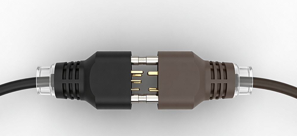
Communication connectors, as key media for signal transmission, are widely used in communication equipment, data centres, consumer electronics and other fields. Their performance directly affects the stability, reliability and speed of signal transmission.
kz connector
7/25/20254 min read
The following are the main testing methods for communication connectors and their corresponding core performance indicators:
Main testing methods for communication connectors
1. Mechanical performance testing
Communication connectors must maintain structural stability under conditions such as frequent insertion and removal, vibration, and impact. Mechanical performance testing is a fundamental step in this process.
• Insertion and removal force testing
Method: Use an insertion/extraction force tester to simulate the insertion/extraction process of the connector, measuring the insertion force (force required during insertion) and extraction force (force required during extraction).
Purpose: Ensure that insertion/extraction forces remain within reasonable limits (e.g., moderate insertion force for ease of operation, sufficient extraction force to prevent accidental disconnection), avoiding damage to terminals due to excessive force or poor contact due to insufficient force.
Standards: For example, USB connectors require insertion force ≤5N and extraction force ≥0.5N (specific values may vary depending on the standard version).
• Durability Testing (Insertion/Extraction Cycle Testing)
Method: Repeatedly insert and remove the connector a specified number of times (e.g., 1,000 times, 5,000 times, or higher) to observe terminal wear, changes in contact resistance, and mechanical structural integrity.
Purpose: To verify the reliability of the connector during long-term use and ensure its lifespan meets equipment requirements (e.g., industrial-grade connectors require ≥100,000 cycles).
• Vibration and shock testing
Method:
▪ Vibration testing: Simulate the vibration environment during device operation on a vibration table (e.g., random vibration at 10–2000 Hz, acceleration 1–10 g), lasting 8–24 hours.
▪ Shock Testing: Apply instantaneous shock forces using a shock testing machine (peak acceleration 50–500g, duration 0.1–1ms) to simulate transportation or drop scenarios.
Purpose: Ensure the connector does not loosen or break under vibration (e.g., communication base station vibration) or shock (e.g., equipment drop).
• Terminal retention force test
Method: Measure the retention force of the terminal in the plastic housing using a tensile testing machine (e.g., tensile force ≥ 30 N), or detect the displacement of the terminal after insertion/removal (≤ 0.1 mm).
Purpose: Prevent signal interruption caused by terminal loosening due to vibration.
2. Electrical Performance Testing
The core function of communication connectors is to transmit signals, and electrical performance directly affects signal quality.
• Contact Resistance Testing
Method: Use the four-wire method (Kelvin method) to measure micro-ohm-level contact resistance (high-speed connectors require ≤1 mΩ, standard connectors ≤5 mΩ).
Purpose: Ensure efficient current or signal transmission and prevent overheating or signal attenuation caused by excessive contact resistance.
• Insulation Resistance and Withstand Voltage Testing
Method:
▪ Insulation Resistance: Apply a DC voltage of 500V and measure insulation resistance ≥1000MΩ (≥100MΩ in high-humidity environments).
▪ Withstand Voltage: Apply an AC voltage of 1000V or DC voltage of 1500V for 1 minute to detect insulation breakdown.
Purpose: To prevent short-circuit risks in high-voltage environments (e.g., communication equipment power supplies) or high-humidity conditions.
• Signal Transmission Performance Testing
High-Speed Signal Integrity Testing: Test critical parameters for high-speed connectors (e.g., USB4, HDMI 2.1, PCIe 5.0):
▪ Insertion loss (IL): The degree of signal attenuation after passing through the connector (e.g., USB4 requires ≤3dB@20GHz).
▪ Return loss (RL): The degree of signal reflection (e.g., HDMI2.1 requires ≥15dB@6GHz).
• Crosstalk (XTALK): Signal interference between adjacent channels (e.g., PCIe5.0 requires ≤-30dB).
Purpose: To ensure distortion-free transmission of high-speed signals (e.g., 5G communication, high-speed backplanes in data centres).
• Current Carrying and Temperature Rise Testing
Method: Apply the rated current (e.g., 1–10 A) and monitor the connector's temperature rise (typically ≤30°C, ≤50°C in high-temperature environments).
Purpose: Verify stability under high current conditions (e.g., power connectors in communication equipment) to prevent overheating and fire hazards.
3. Environmental Adaptability Testing
Communication connectors must be able to adapt to complex environments (high temperatures, low temperatures, humidity, corrosion, etc.), and environmental testing verifies their tolerance.
• Temperature Cycling and Thermal Shock Testing
Method:
▪ Temperature Cycling: Cycle between -40°C (low-temperature storage) and +85°C (high-temperature operation) (e.g., 10 cycles) to simulate changes from cold to hot environments.
▪ Thermal Shock: Rapidly switch between high temperature (+125°C) and low temperature (-55°C), lasting 30 minutes per cycle, for a total of 10 cycles.
Purpose: To assess the thermal expansion/contraction resistance of connector materials (e.g., plastics, metal coatings) to prevent contact issues or cracking caused by temperature differences.
• High Humidity and Salt Spray Testing
Method:
▪ High Humidity Testing: Conducted at +85°C and 85% RH for 1,000 hours to monitor changes in insulation resistance.
▪ Salt Spray Testing: Sprayed with a 5% NaCl solution for 96–240 hours to observe surface corrosion.
Purpose: To verify the connector's corrosion resistance in coastal base stations or tropical regions.
• Dust and Water Resistance Testing (IP Rating Testing)
Method: Conduct immersion testing (1 metre water depth for 24 hours) or pressurised water spray testing (IP69K) according to IP standards (e.g., IP67/IP68) to assess sealing performance.
Purpose: To ensure the protective capability of outdoor communication equipment (e.g., 5G base stations, vehicle-mounted communication systems).
4. Special Performance Testing
For specific application scenarios of communication connectors, targeted testing is required.
• EMC (Electromagnetic Compatibility) Testing
Method: Simulate electromagnetic interference environments (e.g., radio frequency interference, static discharge) in an EMC laboratory to test the connector's shielding effectiveness (SE ≥ 60 dB) and interference resistance.
Purpose: Prevent electromagnetic interference from causing signal distortion (e.g., communication base station antenna connectors require high shielding performance).
• Flame Retardant and Fire Resistance Testing
Method: Test flame retardancy according to the UL94 V-0 standard (flame extinction time ≤ 10 seconds) or simulate equipment fires (700°C high temperature for 30 minutes).
Purpose: Ensure that connectors do not contribute to fire spread, safeguarding the emergency functionality of communication systems.
• Terminal creep resistance testing
Method: Apply continuous loading at high temperature (+85°C) and high current (120% of rated value) for 200 hours to detect deformation of the terminal contact surface.
Purpose: Prevent terminal loosening or increased contact resistance caused by long-term current exposure.
Testing Standards and Certification
Communication connector testing must comply with international and industry-authoritative standards, such as:
• USB-IF: Mechanical, electrical, and compatibility standards for USB connectors (e.g., USB4 Gen3 requires bandwidth ≥ 40 Gbps).
• HDMI Forum: Signal integrity standards for HDMI connectors (e.g., HDMI 2.1 supports 8K@60Hz).
• PCI-SIG: Electrical performance standards for PCIe connectors (e.g., PCIe 5.0 bandwidth ≥ 32 GT/s).
• IEC 60512: General connector testing methods (contact resistance, insulation resistance, etc.).
• MIL-DTL-38999 (military standard): High-reliability connector requirements for high/low temperature, vibration, etc.
Communication connector testing covers four key dimensions: mechanical, electrical, environmental, and special performance. The core objective is to ensure high-speed signal transmission, low loss, and high reliability. Through rigorous testing and certification (e.g., USB-IF, HDMI Forum certification), connectors can be guaranteed to operate stably in communication devices, data centres, and other scenarios, meeting the high-speed interconnection requirements of technologies such as 5G, IoT, and cloud computing.
Connectors
Quality electronic connectors for diverse applications.
Key Account Manager
Welcome inquiries
E-mail : jojo@kzconnector.com
TEL: +86-13538668046 Jojo
2021.All rights reserved for Shenzhen Kangzheng Electronics Co., Ltd.
Add:FTY1: Building 8, Lane 4, Yuanzhou, Ludong Community, Humen Town, Dongguan City, Guangdong Province, China.
FTY2: Building 1, Huitong Shuipingxi Electromagnetic Information Industrial Park, Huaihua City, Hunan Province, China.